7. SSD1306 OLED Display with I2C
Connect a 3.3 V-compatible, four-pin, 128×64 SSD1306 I2C module to the Pi's I2C header, then send HELLO PI with the downloadable C++ program below. No Python library or external font is required. Start with one still image, not an animation or a bus-speed change.
Sample code on GitHub
Sample and README · C++ source · CMake build instructions
The repository's CMake target is oled_hello; its source file is named main.cpp. The direct-build instructions below remain available. This is the current standalone example, not yet the separate SSD1306 library-based version.
Before you start
This lesson adds I2C display output to C++ Hardware Programming. You need a working Raspberry Pi OS installation, four jumper wires and the exact module's pinout and voltage specification. Complete Development Setup before starting; no motor circuit is required. Commands below run on the Pi, either in its terminal or over SSH.
This example is for an SSD1306 module with an internal charge pump. An SH1106 display, 128×32 panel, SPI module or bare controller needs different handling. Similar appearance and an I2C acknowledgement do not identify the controller.
Our validation board is a Raspberry Pi 4B. The wiring table uses the standard 40-pin header; it does not apply to a Pico. Read module labels: different boards arrange their four pins differently.
1. Wire the display with power disconnected
Shut down the Pi and disconnect power before wiring. Disconnect other supplies that could keep the circuit powered too.
| OLED label | Pi physical pin | Pi signal |
|---|---|---|
| VCC | 1 | 3.3 V power |
| GND | 6 | Ground |
| SDA | 3 | GPIO2 / SDA1 |
| SCL | 5 | GPIO3 / SCL1 |
Physical pin 3 is GPIO2, not GPIO3. Locate pin 1 from your board's documentation, not an assumed viewing angle. Check every connection before restoring power.
Pi GPIO signals use 3.3 V logic. Do not move VCC to 5 V to fix a blank panel: a module's pull-ups may then expose SDA/SCL to 5 V. Use a documented 3.3 V-compatible module or design the appropriate interface first.
2. Check the I2C interface and permissions
After powering up and signing in, run:
The device should exist. On our Pi it belongs to root:i2c, with group read/write access, and the login user belongs to i2c. Your OS may use a different permissions policy; inspect it rather than compiling or running everything as root.
If the interface is disabled, use sudo raspi-config, choose Interface Options → I2C, and enable it. Follow any reboot instruction. For a headless Pi, first confirm that SSH and your recovery access are configured; see initial setup.
If your OS uses the i2c group but your account is missing from it, an administrator can add the account:
Sign out completely and sign in again, then repeat id -nG. Do not use world-writable device permissions as a shortcut.
Use the module's documented 7-bit address, usually 0x3c or 0x3d. This example accepts only those two addresses. 0x78 and 0x7a are not the 7-bit addresses to pass to Linux. Our connected module responds at 0x3c; that is not a promise about your module.
Stop other applications that own this display before proceeding. Do not force access past a kernel driver or run two drawing programs simultaneously. This guide does not require an all-address bus scan or i2c-tools.
3. Download and compile the standalone example
Download oled_hello.cpp, or run these commands on the Pi in a new project directory:
The directory contains your downloaded source and executable; no boot configuration is changed. Inspect the source before running it. A successful compiler normally prints nothing. If g++ is missing, follow the development setup lesson rather than skipping the diagnostics.
The file includes its MIT license and attribution. It is self-contained: you do not need access to a separate Git repository, CMake or a third-party font package.
4. Test without opening the display
Expected output:
This checks the program's framebuffer construction only. It does not check permissions, the address, wiring or visible pixels. Keep 0x3c only if it matches your module; use 0x3d consistently if that is its documented address.
5. Send HELLO PI, then look at the screen
After completing the electrical and ownership checks, explicitly enable output:
Expected terminal output:
The intended result is HELLO PI near the centre of the panel. Terminal success means Linux accepted the transfers, not that the pixels were visually verified. Look at the actual panel before calling the project complete.
The program exits after one frame. The display can retain that image while powered; no background process is required. Avoid leaving static text lit unnecessarily. Turn the panel off when finished:
This sends Display Off; it does not disconnect power or undo I2C configuration. Run --show again to initialise and draw again. After a power cycle, rerun the program; enabling I2C does not automatically launch a drawing application.
What the C++ program does
A 128×64 monochrome frame occupies 128 × 64 ÷ 8 = 1024 bytes. Each byte holds eight vertically adjacent pixels. Pixel (x, y) sets bit y % 8 in byte x + (y / 8) * 128.
The program opens /dev/i2c-1, selects one slave address with I2C_SLAVE, configures horizontal addressing and sends the frame. A command transfer starts with control byte 0x00; display data starts with 0x40. Neither is the device's I2C address.
Each data transfer carries up to 31 framebuffer bytes plus the control byte. The panel stays off during initialisation and turns on after the complete frame is sent. Short or failed writes stop the program with a nonzero exit status, rather than silently claiming success.
The font deliberately contains only the letters needed for HELLO PI. Changing the string to arbitrary text requires adding glyphs or integrating a suitably licensed font; this is a first-display example, not a general graphics library.
If the screen stays blank
| Symptom | Check next |
|---|---|
/dev/i2c-1 does not exist |
I2C interface configuration and the OS's bus enumeration |
Open I2C: Permission denied |
Device ownership and groups in the current login session |
Select I2C address: Device or resource busy |
A kernel driver may already own the address; do not force access |
I2C write: Remote I/O error or another transfer error |
Documented address, SDA/SCL, common ground and module power; power down before rewiring |
| Transfers pass but the screen is blank | Exact controller, 128×64 geometry, charge-pump compatibility and physical power connection |
| Cropped or shifted output | A different geometry/controller, especially 128×32 or SH1106; do not assume the init sequence is interchangeable |
| Display works until reboot | Drawing and I2C enablement are separate; rerun --show before designing an autostart service |
Change one layer at a time. Reinstalling the OS, raising voltage or overclocking I2C is not the first response to a wiring or controller mismatch.
Real hardware and verification limits
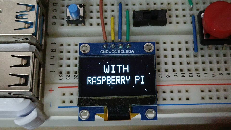
This photograph is from our earlier title-animation recording on the same project's SSD1306 display. It is not a photograph of this HELLO PI example. You can watch that real recording on the homepage.
For this article on 14 October 2026, the standalone source compiled on a Pi 4B with Debian 13-based Raspberry Pi OS, kernel 6.18.50+rpt-rpi-v8 and GCC 14.2.0. Both the dry run and the actual --show transfers to /dev/i2c-1, address 0x3c, completed successfully. Visual confirmation of the new greeting was not available when these results were recorded.
The existing test machine has I2C configured at 400 kHz. This tutorial does not change that setting or claim a measured frame rate. Enabling I2C and changing group membership were not executed for this revision because the test machine already had access.
Check your understanding and continue
Can you distinguish physical pin 3 from GPIO3? Why does a successful dry run not prove that the screen works? What is the difference between the I2C address and the data control byte?
Return to the course overview to review GPIO, PWM and I2C. Once your first frame is visibly correct, animation adds a rendering loop, timing and shutdown handling; it is a separate step, not needed to diagnose a blank display.
Technical references: Raspberry Pi GPIO documentation, Linux I2C device interface, and the Solomon Systech SSD1306 datasheet.